Shopping Cart
There are no more items in your cart
 English
  Polski
Motion System 3dof
20,325.20zł

346.34zł
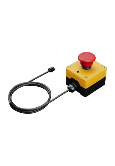
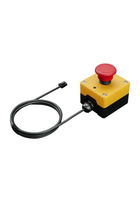
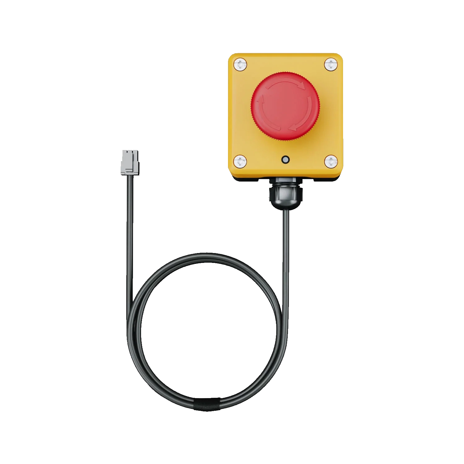
The Qubic System Motion-Lock Switch is a wired, dual-state control for the MOTION-LOCK subsystem. Pressing the switch immediately stops connected compatible Qubic System devices, while the dual-channel design also monitors the wiring. Two independent contacts, an integrated status LED and support for daisy-chaining multiple devices make it easier to control an advanced motion setup.
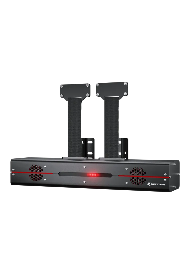
Qubic System QS-BT1 is a dual-channel Direct Drive belt tensioner that turns telemetry into pressure felt across the driver's shoulders. Each channel delivers up to 200 N, allowing the system to communicate braking, cornering, gear shifts, engine vibration and loss of grip. It works as a standalone device or alongside a motion platform, supports racing and flight simulators, and connects directly to a Windows PC through USB.
6,008.13zł
You might also like
| Parameter | Data |
|---|---|
| Product name | Qubic System Motion-Lock Switch |
| Official manufacturer name | MOTION-LOCK Switch |
| SKU | QS-SBML-1 |
| Product type | Wired, dual-state motion stop switch |
| Supported subsystem | Qubic System MOTION-LOCK |
| Operation | Hardware stop command for connected compatible devices when pressed |
| System architecture | Dual-channel hardware and software design |
| Electrical contacts | Two independent contacts; a single-contact failure does not prevent a stop and is detected by the subsystem |
| Cable monitoring | Detection of disconnected, damaged or incorrectly connected MOTION-LOCK wiring |
| LED indication | Flashes while a device is moving; remains steadily lit after stopping |
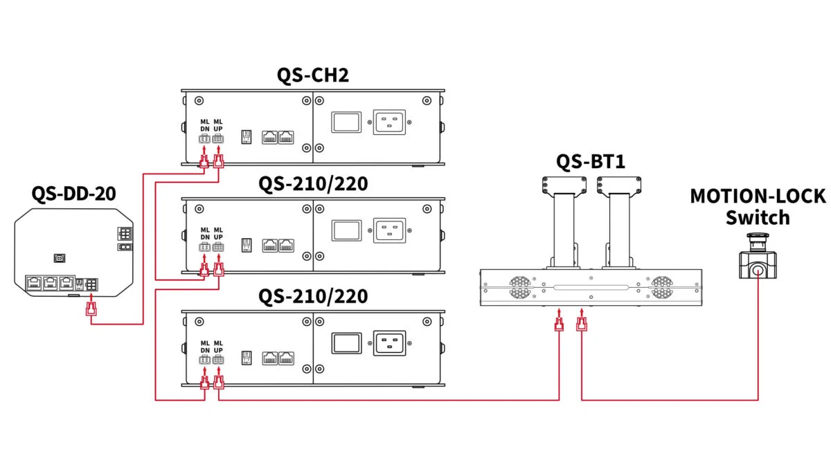
| Device connection | Daisy chain through input and output connections; independent circuits are also supported |
| Number of devices in one chain | Virtually unlimited according to the manufacturer, without reducing subsystem performance or reliability |
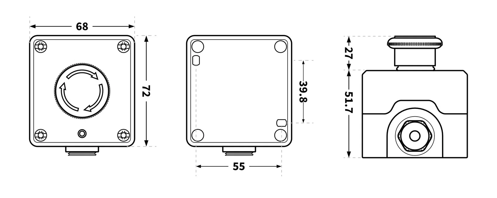
| Enclosure dimensions | 68 × 72 × 51.7 mm |
| Button projection above enclosure | 27 mm |
| Mounting-point spacing | 55 × 39.8 mm |
| Switch component standards | IEC 60947-5-1 and VDE 0660 |
| Quality control | Every unit is manually tested before shipment |
| Country of manufacture | Poland, European Union |
| Device | Compatibility | Notes |
|---|---|---|
| Qubic System QS-210 | Yes | The switch is included with the platform as standard |
| Qubic System QS-220 | Yes | The switch is included with the platform as standard |
| Qubic System QS-S25 | Yes | The switch is included with the system as standard |
| Qubic System QS-V20 | Yes | The switch is included with the system as standard |
| Qubic System QS-BT1 | Yes | Optional accessory; the QS-BT1 can operate without a separate switch |
| Qubic System QS-CH2 | Yes | Optional accessory; the device normally connects to a QS-210 or QS-220 system, so an additional switch is usually unnecessary |
| Qubic System QS-DD-20 | Yes | Can operate in the same chain or on an independent MOTION-LOCK circuit |
| Other Qubic System devices | Conditional | A MOTION-LOCK subsystem is required; check the current manufacturer compatibility guide for the specific hardware revision and any required adapter |
When pressed, it stops connected devices that support the MOTION-LOCK subsystem. It can control a single device or an entire chain of compatible components.
Yes. MOTION-LOCK combines hardware and software functions, while the stop request is handled directly by the subsystem. Its response therefore does not depend on in-game button support.
It works with Qubic System products equipped with the MOTION-LOCK subsystem. Confirmed examples include the QS-210, QS-220, QS-S25, QS-V20, QS-BT1, QS-CH2 and QS-DD-20.
Yes, it is included as standard with systems including the QS-210, QS-220, QS-S25 and QS-V20. A separately purchased unit can serve as a replacement or an additional control point for a compatible configuration.
Yes. Devices can be daisy-chained through their MOTION-LOCK inputs and outputs. The manufacturer describes the number of units supported in one chain as virtually unlimited.
Yes. This allows different device groups to be stopped separately, for example the motion platform, QS-DD-20 wheel base and QS-BT1 belt tensioner.
The two independent contacts provide two control channels. If one contact fails, the other can still stop the device, while the MOTION-LOCK subsystem detects and reports the fault.
The LED flashes while a device is in motion. It remains steadily lit after the system has stopped, making the current state easy to identify.
Install it close to the user, within easy reach from the driving position. The manufacturer recommends testing its operation at least once a month and after any wiring changes.
No. The MOTION-LOCK input is not SIL- or PL-rated and does not guarantee functional safety. It is designed to stop compatible devices; installations requiring certified energy isolation must use appropriately engineered external safety equipment.
Simline is the largest authorised distributor of Qubic Systems in Poland and Europe. As an authorised Qubic Systems partner, all products from this brand are covered by full warranty protection for up to 2 years within the European Union, in accordance with Qubic Systems warranty terms.
Simline.eu is an authorised Qubic Systems partner, so we act as an intermediary in the warranty process and handle submissions. Please email support@simline.eu or qubicsystem@simline.eu with photos and videos showing the defect, a description of the issue, and pack the equipment for collection.
You might also like